Galvanic Anode Cathodic Protection (GACP) vs. Impressed Current Cathodic Protection (ICCP): Which CP System is Right for my Project?
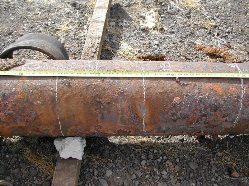
Corrosion is a primary concern for pipelines as it can cause significant damage to the pipeline structure and potentially lead to leaks, which can be costly to repair and environmentally harmful. Cathodic protection (CP) systems help minimize the risk of pipeline leaks and damage by providing protection from potential corrosion issues. Regular monitoring and testing of cathodic protection systems confirm that the pipeline is adequately protected. Monitoring pipe to soil potentials offers early corrosion detection before it becomes a serious problem.
If you’re new to corrosion prevention and cathodic protection, take the time to read one of these articles to develop a better understanding of cathodic protection:
What is Cathodic Protection (CP), and how does it protect infrastructure?
4 Key Factors in Estimating Cathodic Protection System Costs in Your Pipeline
Often, the first decision the design engineer, owner, and operator of a pipeline needs to make after determining whether the soil is corrosive is whether to use a Galvanic Anode Cathodic Protection (GACP) or an Impressed Current Cathodic Protection (ICCP) system.
There are guidelines for when to use each system type based on soil resistivity and the structure surface area. While these guidelines can help steer your cathodic protection design decisions, each project has unique requirements to consider, and it is best to consult with a corrosion engineer or certified specialist.
Galvanic CP Systems
Within certain limits, galvanic anodes offer a relatively inexpensive and convenient means of controlling corrosion. In a galvanic CP system, the anodes are constructed from an active metal, such as magnesium or zinc. The electrical potential available to produce the flow of direct electric current is limited to the difference in potential between the magnesium or zinc and the steel pipeline. The driving voltage between the anode and the pipeline results in corrosion of the anode and current flow to the pipeline. Using galvanic anodes is usually economical in applications where the pipeline has a dielectric coating, a diameter of 48 inches or less, and the soil resistivity is less than 3,000 ohm-cm.
Galvanic anodes have an insulated copper lead wire connected to the anode at one end. The free end of the lead wire is terminated in a test station for monitoring. The test station includes a terminal board and terminals for landing the anode lead and pipeline drain wires. Installation of a test station allows the pipeline potential and anode current to be measured and monitored to ensure the system’s proper operation. A schematic showing a galvanic CP system is shown in Figure 1.

Figure 1. Galvanic CP System Schematic
Impressed Current CP System
Impressed current CP systems use a power source to impress current from an external anode through the soil to the structure. The impressed current anode is constructed from an inert material, such as cast iron. A wire from the negative terminal of the power source (typically a rectifier) is connected to the pipeline, and wires from the positive terminal are connected to anodes. A schematic of an impressed current CP system with a rectifier and anodes in a deep well (one possible anode configuration) is shown in Figure 2.
Power is typically sourced as alternating current (AC) from the electrical grid that is then rectified to direct current (DC). Existing AC power at structures and transformers are used as much as possible. When possible, rectifiers will be located near manholes, along access roads, or in other areas that provide convenient access. Alternate power sources, such as solar systems with photovoltaic panels, batteries, and charge controllers, can also be used.
An advantage of the impressed current CP system is the ability to adjust the amount of protective current applied to the structure and protect several miles of pipe from one current source. Impressed current CP systems generally apply when AC power is available, the structure has a large surface area or is bare or poorly coated, and the soil resistivity is greater than 3,000 ohm-cm.

Figure 2. Impressed Current CP System Schematic
Both GACP and ICCP systems can be effective in preventing pipeline corrosion. Still, the specific type of cathodic protection system for a given pipeline will depend on several factors, including the material and size of the pipeline, the location and environment in which it is installed, and the expected corrosion rate. A corrosion engineer or specialist can help you to determine the most appropriate type of cathodic protection system for your pipeline project.
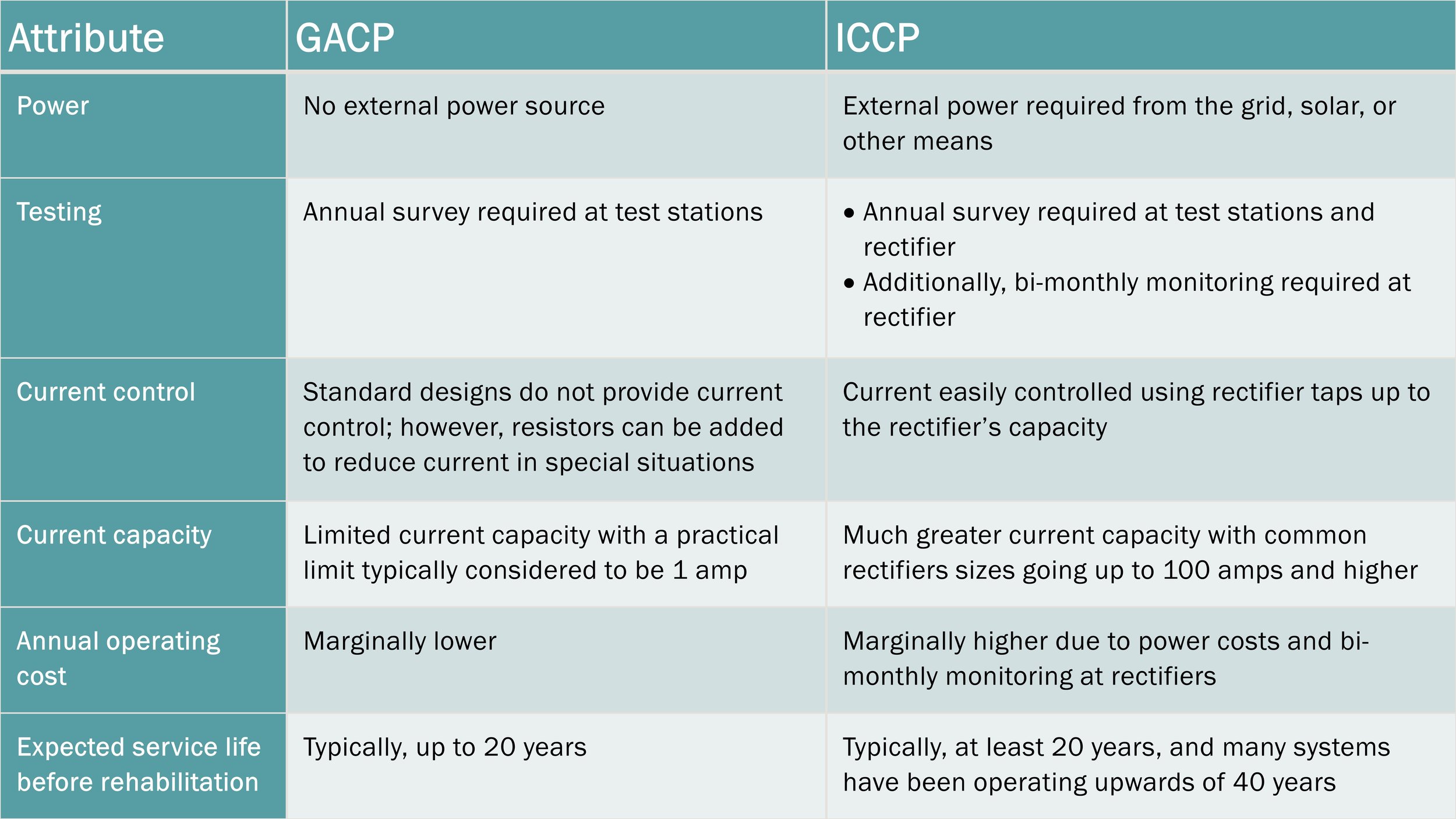
Operational considerations for each type of cathodic protection system are provided in the following table. Each attribute listed will impact the capital (design and construction) and ongoing operation costs for your pipeline project. During the cathodic protection system design phase, an engineer or specialist can review in detail the factors that affect both the cost and operability of a cathodic protection system so that you can make a well-informed decision.
At V&A, we are passionate about protecting infrastructure assets from the harmful effects of corrosion. Our field-based engineers assist water and wastewater clients nationwide in evaluating the need for and designing the appropriate cathodic protection systems for new and existing pipelines. We are available to answer your corrosion-related questions and provide cathodic protection design support. Feel free to use the link below to reach one of our corrosion engineers.